Utilising the new FREE topology optimisation ACT-extension, one can explore new innovative ways to reduce mass that were not available before. The DoE (Design of Experiments) approach may not be feasible if the design’s shape is not yet defined, while creating CAD models to capture all the potential design possibilities may be impossible.
Now imagine starting with an arbitrary volume and having each element within either turned on or off to create the most optimum shape, taking into consideration the applied loads, boundary conditions, and design constraints (such as, a maximum displacement/stress limit required for the design) to achieve an overall weight reduction.
In Shape Optimisation, we have constraints and objectives. Constraints define the optimisation’s bounds, while objectives are essentially the goal of the optimisation problem.
In the following example, the imposed loadings on the Bell Crank must not result in excessive deformation, but the component is way too heavy so mass needs to be removed.
Watch the video to see the topology optimisation ACT-extension in action or read on below:
If you would like to see the full demonstration of this process you can watch the complete video here (43 minutes).
The model setup.
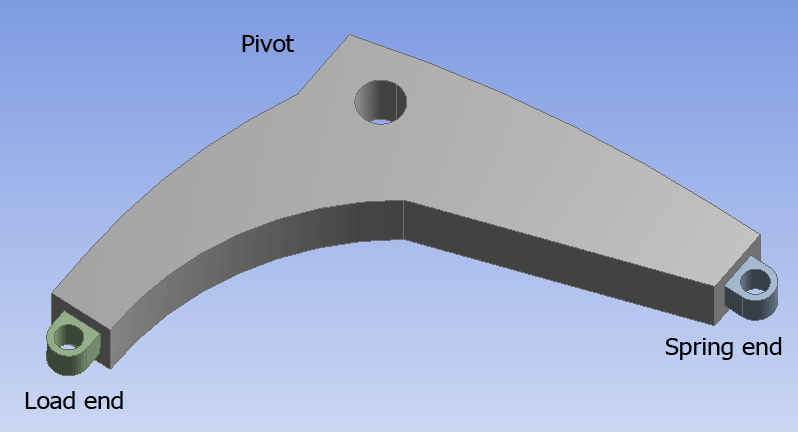
The remote point locations shown below (at all hole centres) used to define a revolute joint, load and spring-to-ground connection.
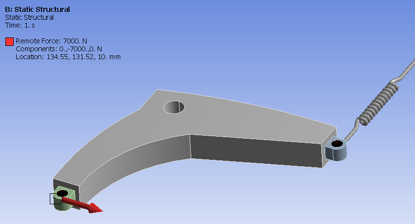
The results show a lot of low-stress regions. We could iteratively remove material and rerun analysis (through trial and error) but we would only be considering 1 load-case.
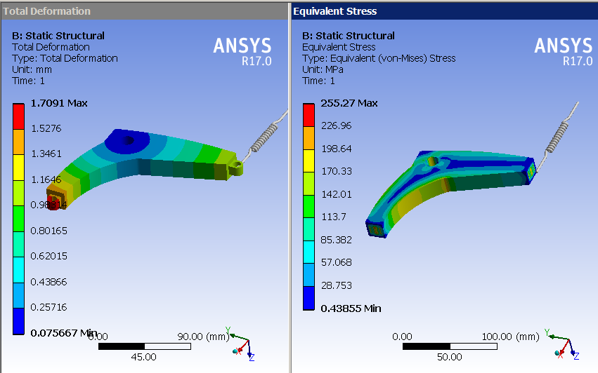
ANSYS Topology Optimisation, available when the ACT is loaded within the project.

Inside ANSYS Mechanical, the topology optimisation toolbar.

Setting up a topology optimisation starts with a drag & drop over the Static Structural system on the project page.
Inside ANSYS Mechanical, the completed setup.
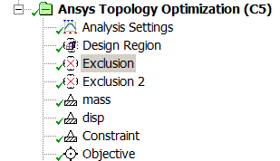
Definitions for specified regions where mass can be removed, or excluded from mass-removal, as well as objectives. (e.g. mass reduction targets, displacement limits, etc.)
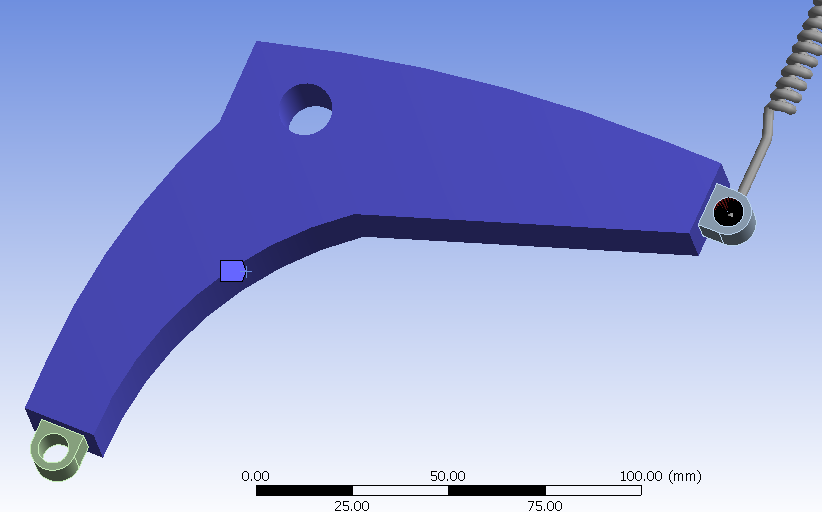
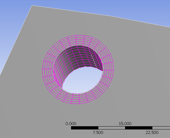
The blue solid is where mass can be removed and the cylinder of pink elements will be excluded from mass removal as it is a major load-bearing area. An inflation layer was used here to get a ring of elements around the pivot hole. The faces where the spring and load lugs mount are also excluded to allow for a mounting face.
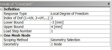
The displacements in Y and Z directions cannot be more than 3 mm in the negative direction, this is an optimisation constraint, its location near the load. The upper bound is specified as a positive number, based on the load this will never be violated, a value of zero would imply infinite stiffness, so it should never be used.
The mass reduction is another constraint, here the percentage refers to percentage of what is left over after exclusion, so purely by exclusion mass has been removed, and is not included in the percentage reduction consideration, this must be kept in mind when setting mass targets, and can result in a failed solution. Alternatively a range can be set, to impose less constraint on the optimisation problem.
Once the solution completes, a contour of 0 -1 is created, this can be nodal based or element based. The nodal based value is better for visualisation. A capped isosurface is created, this shows the solid with underutilised elements removed. Moving the slider to a point that produces a viable solid is the aim here, as this is written out to an STL file for further processing.


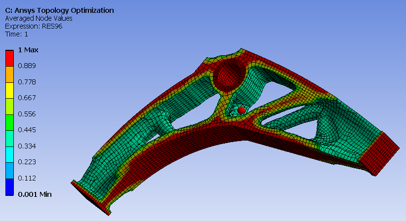
This capped isosurface is written out as an STL file by right clicking on the result and choosing export as STL file.
This STL file is then opened in SpaceClaim and manipulated using reverse engineering tools, the aim to recover a solid.
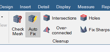
Sometimes the STL may not be watertight so the auto fix is used to clean it up, as the shrink wrapper may do some strange things if the starting point is not a watertight STL. An imperfect STL shows holes or cracks.
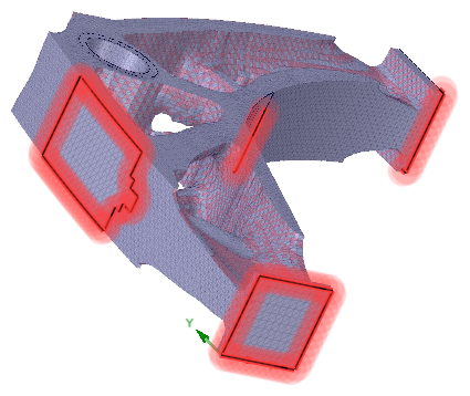
The gap in this solid is a significant feature.
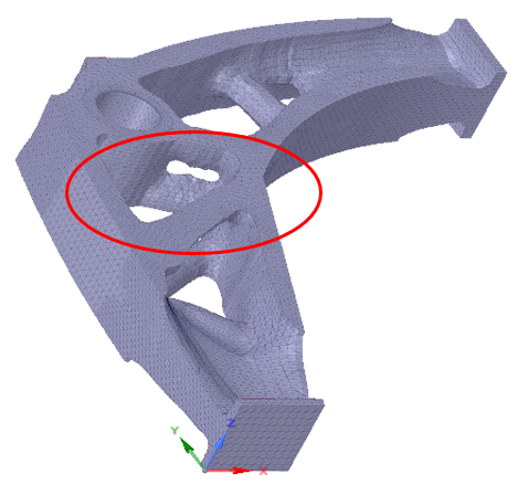
The shrink wrap from the Faceted Data tab is applied, selecting a size that doesn’t defeature too much away, a good guide, use the element size or smaller, half element size gives good results.
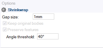
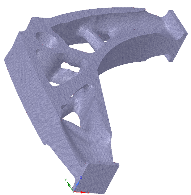
Shrink wrap and 1 smooth level.
We then can either directly convert to solid, or overlay skins that approximate the geometry.
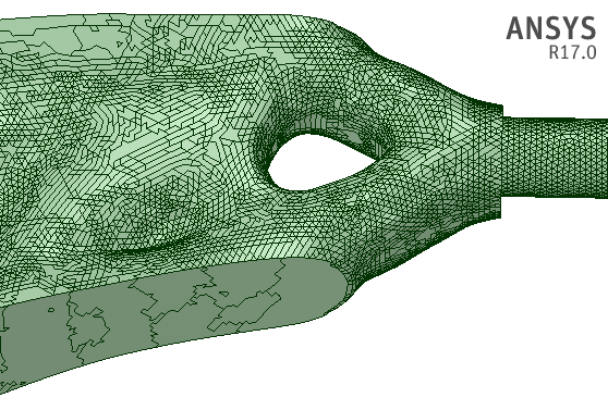
At this stage we can take solid to ANSYS Mechanical and mesh it but because it has so many face patches the need for virtual topology arises, or one can use a patch independent tetrahedron mesh to walk over the sometimes small face patches.
Taking the convert to solid option:
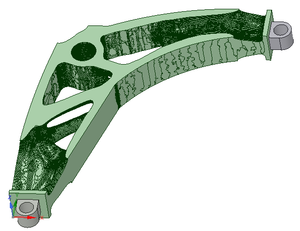
We switch out the optimised solid for the original solid, and import into ANSYS Mechanical. Some items go missing, and need a geometry assignment.
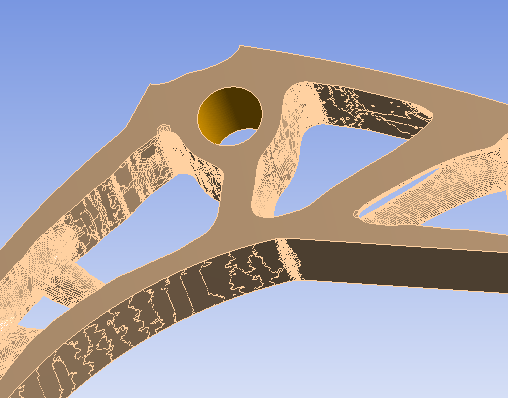
Virtual topology applied to hole, it is composed of many small facets, this face is used as pivot point remote point location and also for a co-ordinate system, everything else is attached to unchanged parts, contacts are done automatically.
All that remains is to apply a patch independent tet mesh, using a size of 3.5 mm max and 3 mm min give a mesh that walks over the small faces, there are just over 42000 faces in the model.
This is the resulting mesh.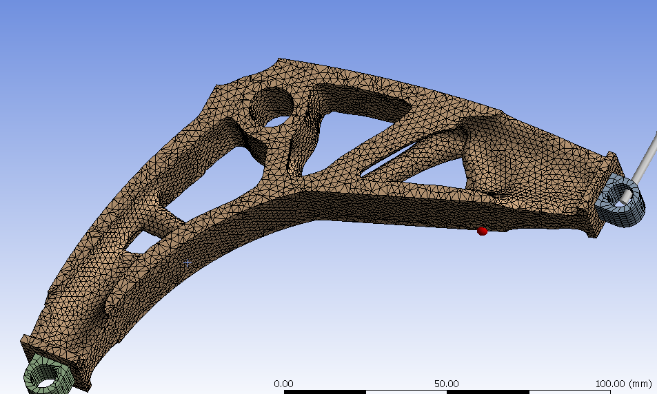
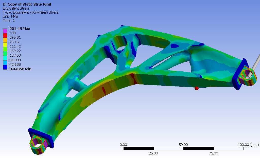 The stress is now higher showing more material is being utilised to carry load, the boss where we elected to keep, is not highly stressed, indicating it could have been thinner.
1.02 Kg compared to 0.46 Kg not quite the 40% we aimed for, but there is no science behind choosing the capped limit.
Some important concepts here:
Only 1 solid optimised so compare parts associatively will aid in having to reconstruct all loads, as only some objects will need attention.
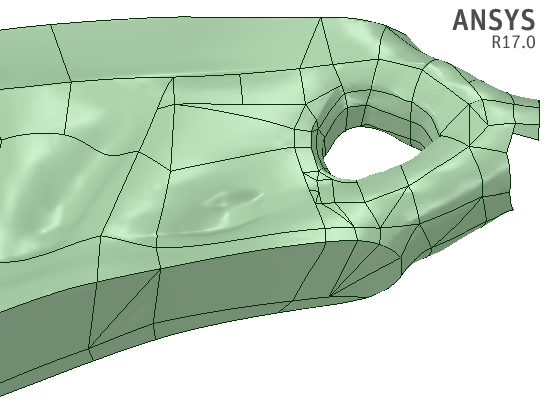
As an alternative to converting faceted mesh to a solid, we overlay skins that approximate the geometry, this gives a cleaner geometry with fewer face patches, and relies on creating a watertight geometry as you go. The skin overlay tools are amazing at capturing the local details. Some planning is required to get good looking faces. The goal is to reduce the many facets to fewer nurbs surfaces, and as a consequence remove the need for virtual topology.
Here we see a facet mesh as output by ANSYS optimiser.
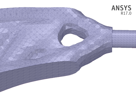
Here we see rough a shrink wrap 2mm used.
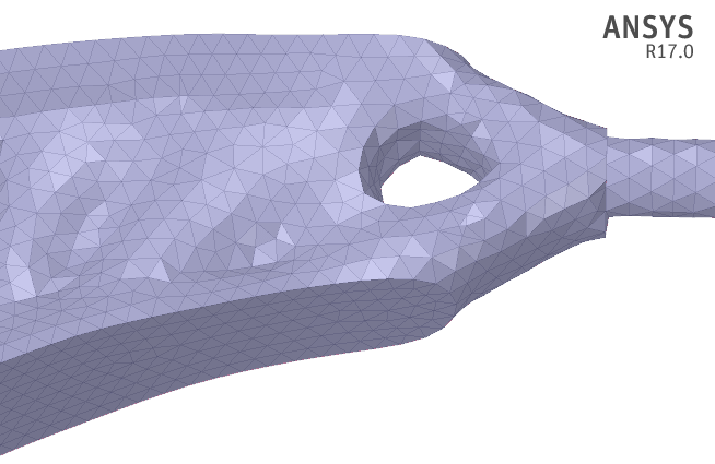
Note the loss of detail
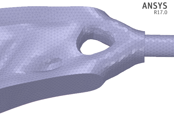
With a setting of 1 mm the detail is retained, the element size used was 2 mm in the FEA mesh.
With 1 level of global smoothing on top of 1 mm shrink wrap:
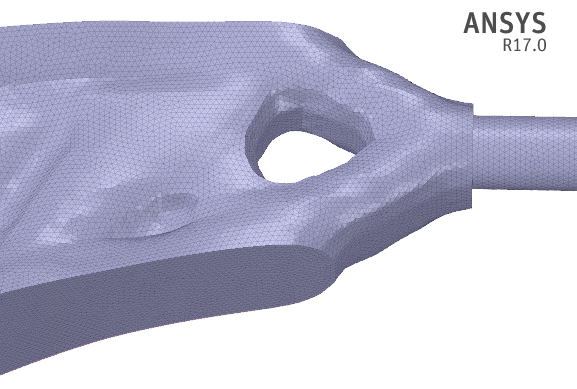
This smoothed mesh is now overlaid with nurbs skins in a series of patches, below is a partially completed geometry
With a straight conversion to solid:
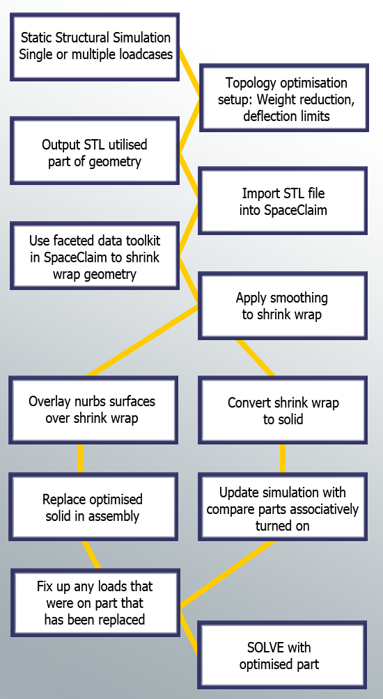
The flow chart below outlines the overall workflow:
More information on ANSYS Topology tools can be found on the SpaceClaim website and this previously published article on ANSYS GTAM.


Topology Optimization is a different how beautiful concept.from where, i can get the extension file? Expecting reply.
Hello. Really interesting article! I am a mechanical engineering student using Ansys 17.0, but I can not download the FREE topology optimisation ACT-extension from Ansys customer portal. Is there any other way to download and install it?
Best regards!