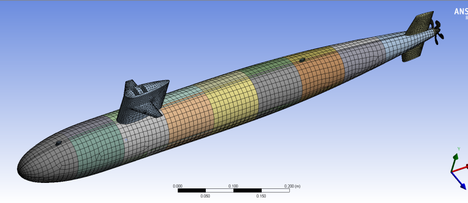
ANSYS Meshing has developed rapidly within the last five years; Body by Body meshing was introduced in 2011 with the emergence of R13, followed a year later by Mesh Connections in R14. A little known feature within R14 is the capability to record and replay meshing strategies in order to increase meshing robustness (See image below).
A new feature within ANSYS R15 is the introduction of parallel part meshing, where ANSYS Meshing will use one core per part within an assembly. The increased speed of mesh generation in R15 compared to R14.5 is very noticeable, with meshing times reduced by at least half for almost every model tested. The great part about this new feature is that it does not require an additional HPC license. Think of this new feature as a free gift from ANSYS!
As a quick test of this concept we meshed a submarine model we had lying around the office. The test model consisted of 24 shell bodies and one solid body. The final mesh contained 19500 nodes and 16767 elements.
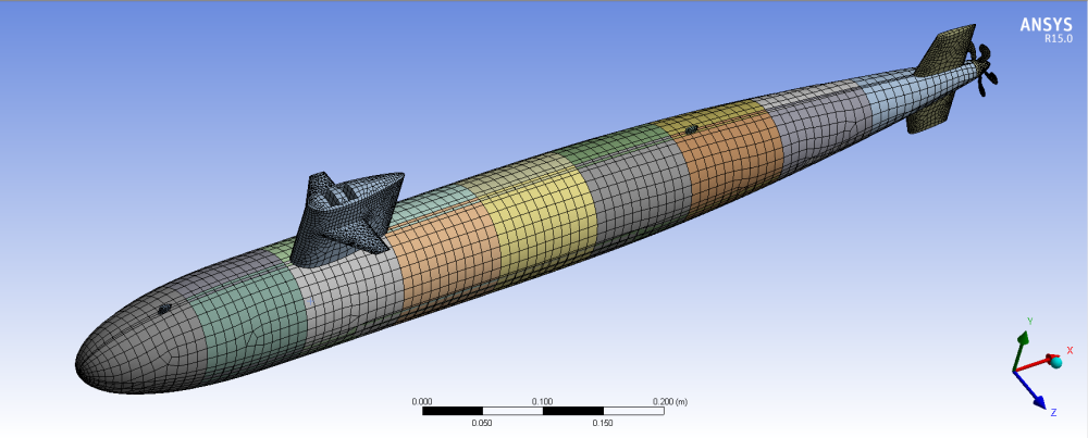
The test machine used for the series of tests was a mid-range laptop equipped with a 1st generation Intel i7 CPU and 8 GB of RAM.
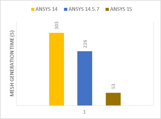
Looking over the test results, the performance gains realised using ANSYS R15 Meshing are considerable:
When compared with legacy products, ANSYS Meshing R15 shows a reduction in meshing time from 5 minutes to less than a minute.
Another newly introduced ANSYS R15 feature was used to generate the above graph – the ability to display the mesh generation time at the completion of a meshing run. To activate this within Mechanical, go to Tools > Options > Miscellaneous > Report Performance Diagnostics in Messages > Yes. Once activated, a message reporting meshing time will be displayed at the bottom of the screen as shown below.
Previous generations of the ANSYS Mesher did not provide a great deal of insight into meshing errors and could only provide a general indication of where the problematic geometry occurred.
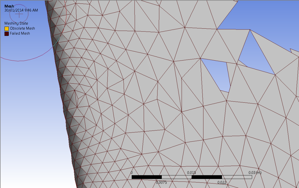
ANSYS Meshing 15 has gone a long way to addressing this issue, with the introduction of mesh colouring and the display of the partially generated failed mesh, showing the exact areas in which ELEMENTS (not bodies as in previous releases) failed to generate. Once the problem areas have been identified it is a simple process to then add local mesh refinement to trouble spots and achieve a successful mesh. Mesh colouring is another great asset in investigating mesh quality, with outdated mesh being displayed in yellow and failed mesh being displayed in red (see below).
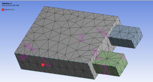
So we have seen that ANSYS R15 is far more capable at mesh generation, yet how are we to analyse mesh quality as is mandatory in numerous industries? In addition to the regular Mesh Metrics statistics available through the mesh details window, it is worth investigating the new Element Named Selection based on Meshing Criterion. For example, in the following Named Selection a filter was applied that would only select elements with a skewness greater than 0.8 and an orthogonal quality less than 0.7.
![]()
The elements selected in the worksheet are then able to be displayed in the graphics tab (see below).
In conclusion, ANSYS have come leaps (no pun intended) and bounds in developing the ANSYS meshing tools, reducing the time taken to generate and debug tricky meshes, leaving more time for the important stuff like result analysis and design optimisation. If you haven’t upgraded already these time savers should convince you that it is time to step up to ANSYS R15.

