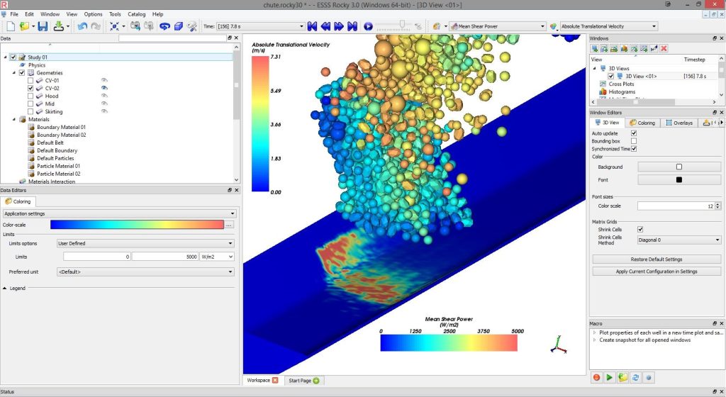
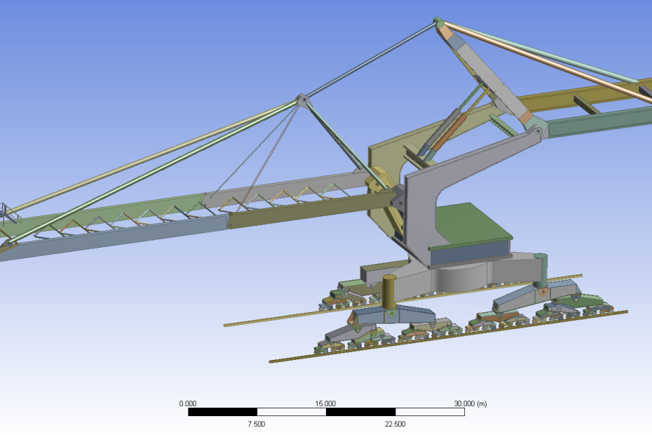
Designing equipment intended for use in the bulk material handling industry is no simple task. Engineers need to consider day to day operating conditions as well as unpredictable loadings such as user error/misuse and erratic weather conditions. Simulation software can optimise machine design and gives engineers the capability to decrease project budgets/timeframes and minimise the loss of raw materials through reduced equipment maintenance and wear.
Traditional design methods involve “rule of thumb” guidelines based upon knowledge acquired through collective experience which, although “tried and true”, raise several problems:
- Hand/spreadsheet calculations are repetitive, every time a design change is made these calculations must be re-evaluated. This manual process requires significant time investment over the duration of a design project as the design progresses through multiple iterations.
- Prototype manufacture and testing is a costly process. The fewer the physical prototypes created and tested, the better. Due to the significant time required to conduct hand calculations, the sample space which can be tested in a given timeframe is inherently limited. This leads to either a) a greater number of physical tests being conducted or b) a smaller number of designs being evaluated, resulting in poorer quality of the end product.
- Implementing FEA in the design process rather than manual calculations reduces the number of assumptions and simplifications being made – realistic loading and detailed complex geometries lead to results of higher accuracy. Higher confidence in the solution leads to less tests being sent through to prototyping and physical testing, reducing time and capital expenditure.
- Large assemblies are particularly difficult to tackle using traditional design methods. ANSYS design tools linked to a supported CAD system[1] allows the end user to create an associative top down parametric design process. The sheer size of a bulk material handling plant results in multiple pieces of interlinked equipment, which would require a considerable number of engineers to audit these designs. Linking ANSYS FEA tools to an upstream CAD system virtually eliminates the data management and versioning issues which would otherwise arise in a typical workflow.
ANSYS contains an extensive library of modules to handle a diverse range of loading conditions a bulk materials handling setup may encounter throughout its lifespan.
Watch the video below to learn more about the applications of FEA in the Bulk Materials Handling Industry.
Linear & Non-linear Static FEA
Linear FEA is now an integral part of modern engineering workflows. The traditional question of “can it be modelled” is almost non-existent, with complex nonlinear problems being solved in hours on desktop PC’s rather than days on supercomputers. The real problem that engineers now face is productivity – “can it be modelled by the deadline”. The ANSYS suite of products has made huge progress into addressing this requirement using a range of techniques such as:
- Automated parallel contact detection algorithm to tackle thousands of contacts in large-scale assemblies
- Parallel part-by-part meshing for faster, more efficient finite element mesh generation
- Efficient model simplification process using automated mid-surface tools
- High Performance Computing capabilities, including multi-CPU and GPU computing
- Mesh assembly capabilities to merge multiple input meshes
- Parametric interaction with CAD systems allowing for automated design optimisation studies
The video below demonstrates the preparation of a complex reclaimer model for FEA using ANSYS SpaceClaim.
These productivity enhancements become progressively more important as the overall model size increases. In the case of the bulk materials industry, a generic large assembly such as an entire reclaimer assembly would typically contain thousands of bodies.
Modal & Harmonic Analysis
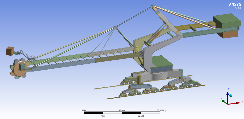
Conveyors, mills & crushers and screens operate around the clock at constant motor speeds. Care must be taken to ensure the operating frequency of the machinery doesn’t approach the resonant frequency for any given structure to avoid premature failure.
Modal analysis within ANSYS Mechanical allows us to calculate natural frequencies for any given assembly; including the ability to account for any pre-stress effects, such as those encountered in guide wires for a drag line assembly.
If the modal analysis predicts a natural frequency which lies close to the operating frequency of the machinery, a harmonic response analysis can be used to predict the magnitude of the sustained oscillations which the structure will vibrate at. The design engineer can use this quantitative data to make an informed decision as to whether that particular vibration mode can be overlooked.
Response Spectrum Analysis
Wind loading and earthquakes pose major challenges in the design process for reclaimers, drag lines and silos. The most efficient way of analysing the response of a structure to these particular loading events is through a response spectrum analysis rather than a traditional time history analysis.
Random Vibration Analysis
The motion of a haul truck travelling across a heavily pitted quarry surface is an inherently random process, meaning it would be very difficult to analyse such a system using a transient analysis. Although the loading is random, we can characterise the motion statistically using a Power Spectral Density (PSD) plot – which can be obtained by fitting strain gauges to the underside of the truck and driving along a surface characteristic of day-to-day operating conditions.
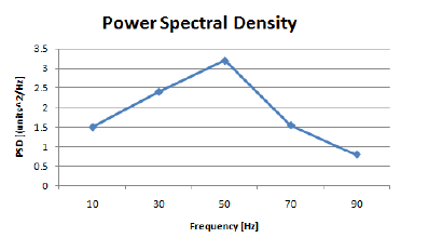
Using the information contained in the PSD, we can obtain a set of results with one standard deviation (using default settings) – i.e. 68.3% of the time the structure’s response will be less than the reported value, ensuring the truck will not experience failure during day-to-day operation.
Watch the video below for a detailed demonstration of setting up and running a static structural analysis in ANSYS.
Fatigue Analysis
Most structures tend to fail due to fatigue rather than static loading. It is imperative that the fatigue life of critical structures be evaluated before a design is approved for manufacture. The bulk materials industry, operating around the clock, 365 days a year, is one field in which this holds particularly true. Failure to do so risks potential costly plant downtime when machinery experiences fatigue failure.
ANSYS nCode Design Life and ANSYS Fatigue Tool are two different means of analysing the fatigue life of a given structure. Using these tools, the user is able to analyse fatigue based upon stress or strain life analysis engines. If strain gauge history based data is available, it can be input into the analysis to gain meaningful fatigue life predictions.
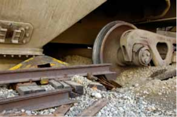
Watch the video below for a short demonstration of the ANSYS Fatigue Tool.
Buckling Analysis
Long, thin structures tend to have a very large change in displacement under essentially no change in axial load. Buckling analysis provides both linear and nonlinear buckling analysis techniques designed to calculate the force at which a structure will buckle.
Cranes, drag lines and reclaimers are made up of a hundreds of slender members. If buckling isn’t taken into account during the design process, the consequences could be disastrous once the equipment makes it into the field.
Rocky DEM
Rocky DEM (Discrete Element Modelling) allows the user to model the flow of bulk materials at the particle scale. Flow trajectories can be observed and optimised. Once a DEM analysis has been completed, the pressure exerted on bin/hopper walls can be exported to ANSYS Mechanical to determine the resulting stresses on the equipment due to the flow of bulk material through the domain.
