General Introduction
Only a couple hundred kilometres above us, low earth orbit (LEO) satellites continue to innovative on the sensing, data transmission and overall capabilities of modern space systems. These satellites can ingest and transmit more information than ever before, allowing constellations of LEO satellites to record data at resolutions and volumes never seen before.
Simultaneously, the dependency we place on these systems-of-systems continues to increase. With satellite technology widely implemented, any outages or complications in space can rapidly cascade down to earth, affecting everything from weather forecasts, to banking systems and national security. As such, it is more paramount than ever to ensure the design of any satellite is robust, future proof and safe.
Digital Mission Engineering (DME) technology enables the simulation of entire space-based missions in a physics accurate, multi-domain environment. This facilitates the consideration of key design requirements across all facets of the mission, from communication links through to satellite survivability and sensor effectiveness. With DME engineering tools integrated throughout the engineering process, a single, unified virtual test environment exists, enabling the user to design a mission with both increased confidence and decreased project timeframes.

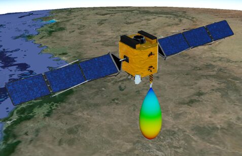
LEO Satellite with Antenna visualised in Ansys STK
This LEAP DME Series will explore the design of a LEO satellite constellation, exploring the implementation of Ansys STK to tackle common design challenges, including the design of a reliable RF communication link, the evaluation of LEO constellations for specific coverage metrics, and the conjunction analysis of the proposed constellation to ensure satellite survivability.
For more information on what Digital Mission Engineering is, check out this post here!
RF Comms Link
Ansys STK facilitates the simulation of physics-accurate RF communications across space, air, land and sea domains. Our hypothetical Design Reference Mission (DRM) starts with the need to model and analyse one such link between a ground facility and LEO satellite. Once this Comms link is defined, we will progress to a full LEO constellation.
In this case the hypothetical ground facility is located near Sydney, atop some sea cliffs. The STK scenario utilises Google’s 3D tileset, streamed straight to STK to bring in accurate geometry down to the street level. Amongst the various terrain modelling options in STK, this level of detail sits in the middle of the available spectrum. Simpler modelling needs might employ STK’s inbuilt terrain server whilst more localised urban 5G/6G telecommunication analysis may opt for even more detailed terrain files with geometry accurate to centimetre resolutions.

Ground Facility Antenna on Sydney sea cliffs tasked with tracking LEO satellite. Local terrain is streamed to STK using Google 3DTillesets
For this DRM, the Google 3D tileset represents a good middle ground, and as a single seamless terrain source for the entire Earth, allows us to reposition the ground facility as required, and immediately compare results with other locations.

The antenna definition tab for the ground facility. Note the other input tabs also available not shown here.
The ground station is comprised of a 14.5GHz Ku-Band Parabolic Antenna, tasked with tracking and receiving data from the LEO Satellite. This Antenna employs an inbuilt parabolic model, however the user may swap this out for a custom gain profile generated in tools such as Ansys HFSS as the project progresses. Doing so can account for the localised installation of their Ku-Band antenna at the platform level. Due to this versatility, STK becomes an incredibly valuable tool throughout the entire engineering process, allowing increased detail to be built into the simulation as project timelines progress.
Additionally, several constraints can be applied to the ground station, from basic line-of-sight to maximum azimuth and elevation tracking rates facilitating an antenna model indicative of any real-world counterparts. Likewise, mission design requirements can be enabled via these constraints, such as a minimum Carrier to Noise (C/N) ratio or Bit Error Rate (BER), effectively filtering out any unsuitable periods of access from subsequent analysis and reports.

Example of two constraints applicable to the ground facility.
LEO Satellite
The LEO Satellite is similarly assembled, with a 14.5GHz antenna, capable of tracking the ground facility with each satellite pass. The satellite itself orbits at 700km utilising one of STK’s inbuilt propagators.
As with the ground station, any combination of user-constraints can be applied to the satellite antenna. Commonly this may include maximum tracking speeds, articulation angles, as well as any planned time periods during which the antenna is deemed unavailable.

Visualisation of Parabolic Antenna mounted to LEO satellite.
Results
The first step to analysing the RF Link is to compute access between them. These access calculations are dynamic within STK, such that if the antennas or parent-level platforms were to change, the access calculation would automatically recompute to reflect this. For example, the initial access computation allows us to quickly visualise periods of access in the STK timeline view. If the user were to move the ground facility, or alter the orbit of the satellite, this timeline would automatically update alongside this change. This also applies to changes made to the constraints on either platform. Whilst oversight of a basic scenario such as this one is relatively straightforward, the ability to quickly jump to timeline points of interest in complex, multi-domain simulations becomes a significant aid to situational awareness.

Timeline view showing analysis period and one of the access windows between Ground Facility and LEO Satellite
As with all objects in STK, several report and graph outputs are made available for the RF Comms Link. Various link budget reports provide insight into the suitability of each satellite pass when compared with any design requirements the user might possess.
Below, a snippet of one such link budget reports shows the computed results including the Equivalent Isotropic Radiated Power (EIRP), Carrier to Noise Ratio(C/N), Bit Error Rate (BER) and more. Not pictured here, these reports also report losses due to atmospheric, rain and any other propagation models enabled by the user.

Snapshot of one of the Link Budget Reports available within STK, more data providers are available within the “detailed” Link Budget reports.
We can also inspect any of the above outputs as a graph or live Data Display within STK. Both options provide quick ways to investigate the real-world implications of interconnected design choices at the system level, as well as powerful visualisation tools for inter-team communication.

Graph of Bit Error Rate for a single LEO Satellite Pass

Visualisation of LEO Satellite with live data display. When played within STK this data updates in real-time.
With this information the user can evaluate each access period to discern the useable access duration of each pass, taking into account design requirements unique to their communication needs. Any change made to the RF Transmitter or receiver is instantly reflected in these results, allowing for the rapid exploration of potential design variations.
What Next?
With the base DRM assembled, the user can now expand further on their mission analysis. Not only are they free to test potential design choices, but to stress-test their system against planned and potential challenges.
Suppose the system featured multiple ground facilities. What happens if one of those ground facilities has an unplanned outage? Do we still have a sufficient access duration across the remaining facilities to receive all necessary information from our satellite? The ability to simulate these plans is pertinent to the design of a reliable, fit-for-purpose space mission.
Join us in part two of this series as we expand to a full LEO constellation, designing and evaluating various coverage metrics across a target area of interest.

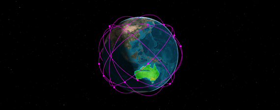
LEO Constellation to be designed in Part 2 of this series.

