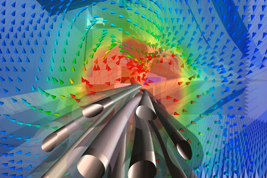
For engineers focused on accurately simulating EMI/EMC effects on larger platforms such as aircraft and full vehicles, one of the most crucial elements to include is cables and cable assemblies. In RF and high-power applications alike, cables are adding parasitics to the system, cables are often generating emissions and are susceptible at the same time. We now have access to Ansys EMA3D which is a tool designed to efficiently model all aspects of cabling – from cable routing to harnesses to detailed topology, which opens the door for engineers to replicate tests involving Bulk Current Injection, Immunity Stripline, and Radiated Emission Antenna tests.

Fig.1: EMC tests in Simulation for Pre-compliance: Bulk Current Injection (left-hand side) and Antenna Test for Radiated Emissions (right-hand side)
It is wrong to think that charge and discharge phenomena, and related technical challenges, are a niche topic within the field of EMC and do not touch many engineers’ interests. In fact, these challenges are critical for many applications and require solutions in the EMC-related design process – which we see often addressed much later in the design cycle using expensive physical testing procedures.
In particular, unwanted charge and discharge effects across large platforms are constantly in the mind of engineers. Those issues affect the work of PCB designers dealing with high voltages, are a constant challenge for manufacturers of high-voltage equipment, and are a central question for engineers mitigating the risk of lightning strikes.

Fig.2: sending equipment to space: surface charging and internal charging and monitoring for risk assessment.
What is so special about EMA3D?
EMA3D is really about fast model preparation of complex platforms and material stack-ups and complex cable harness assemblies. The FDTD solver with an integrated multi-conductor transmission line solver simulates complex platforms to carry out a full system-level electromagnetic analysis.
Especially for arcing simulations, EMA3D combines electromagnetics with non-linear chemistry of dielectrics and air and therefore provides an accurate and realistic solution for charge and discharge phenomena. Background properties such as humidity and pressure can easily be changed.


Fig.3: Cable Harness inside EMA3D (left-hand side) and associated cable topology (right-hand side)
The key element is a hexahedra mesh that is quickly generated and forgiving towards complex and detailed geometry that are encountered for complex cabling on a large platform, such as a full aircraft or automobile. What engineering challenges does EMA3D address? Ansys EMA3D can be used to address a wide range of electromagnetics simulations, including to predict:- Radiated emissions and coupling from cables and PCB boards inside platforms.

Fig.4: Emissions from a cable tree inside a large automotive platform. The aim is to understand areas of high field intinsity which might violate thresholds for EMC standards.
- Electrostatic Discharge (ESD) according to IEC61000-4-2 ESD and ISO10605

Fig.5: ESD test on a PCB: ESD pulse profiles can be defined according to ESD standards. Visualize fields and compare different solutions.
- Coupling through shields

Fig.6: Studying the effectiveness of shielding of an electronics casing
- Arc Formation in HV Systems

Fig.7: Reproduce the current waveform to tackle EMI concerns while mechanically activating the switch.
These issues above are often encountered by companies in Australia and New Zealand at a late stage in their design cycle, leading to a physical testing and validation process that is expensive and time consuming. To help grow the body of knowledge in this field in our region, we will be following today’s blog with additional case studies which showcase the value of using Ansys EMA3D for EMC simulation. Watch this space, and subscribe to our blog to receive the latest updates!
In the meantime, you can speak to one of LEAP’s EMA3D experts about your specific challenges via this link.

