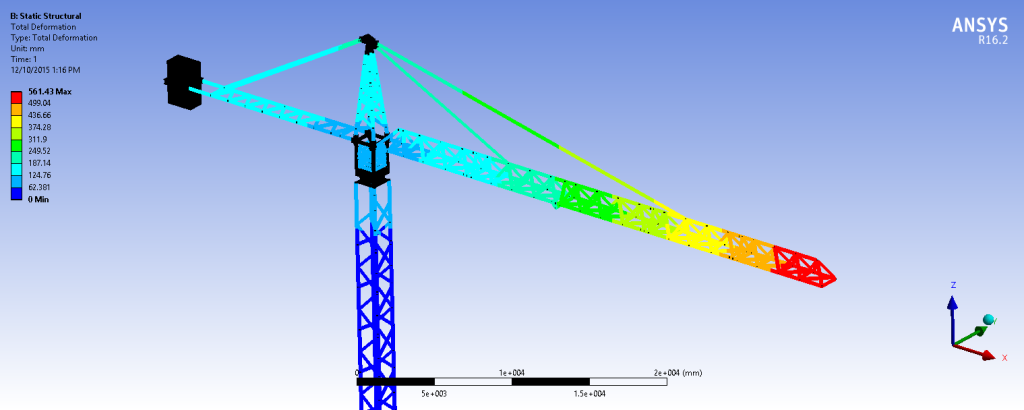
Cranes and lifting equipment pose a unique problem when considered in a finite element analysis. Their sheer size often prevents users from analysing these structures using regular solid elements. Instead, beam elements must be used to reduce the model to a manageable size. The problem with this approach, however, lies in the process of extracting beam elements from the original solid CAD geometry. Meshing and model solution are other issues which may arise if the wrong tools are chosen for the job.
The video below outlines the considerations that should be made when preparing for the analysis of large fabricated structures.
Luckily, ANSYS provides advanced solutions to address common issues encountered throughout a typical FE workflow for cranes and lifting equipment.
Geometry Clean-up and Simplification
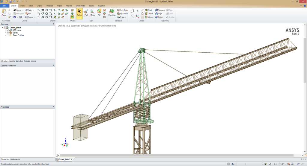
The first, often overlooked, part of the FEA workflow is to clean up incoming CAD geometry and make simplifications to reduce simulation times and computational expense. Although some simplification can be done in the upstream CAD system, ANSYS Spaceclaim Direct Modeler provides a unique set of tools to efficiently convert a generic crane CAD model into a purpose-built FE model.
Beam elements recognisable by ANSYS Workbench can only be created using ANSYS Spaceclaim or ANSYS DesignModeler. ANSYS Spaceclaim, in particular, has the ability to automatically convert solid bodies into line bodies, while simultaneously extracting cross section information from the solid and applying that information to the resultant line body.
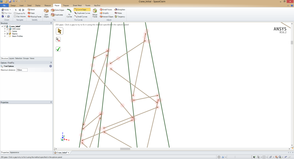
A common issue which arises due to this beam extraction process is the separation of beams which were initially in contact as solids. Spaceclaim’s intuitive auto-extension feature overcomes this problem with ease, merging any nearby beam endpoints which lie within a nominated tolerance value.
Watch a detailed demonstration of how ANSYS SpaceClaim can drastically speed up the process of simplifying large models for FE analysis in the video below.
Meshing Large Scale Geometry
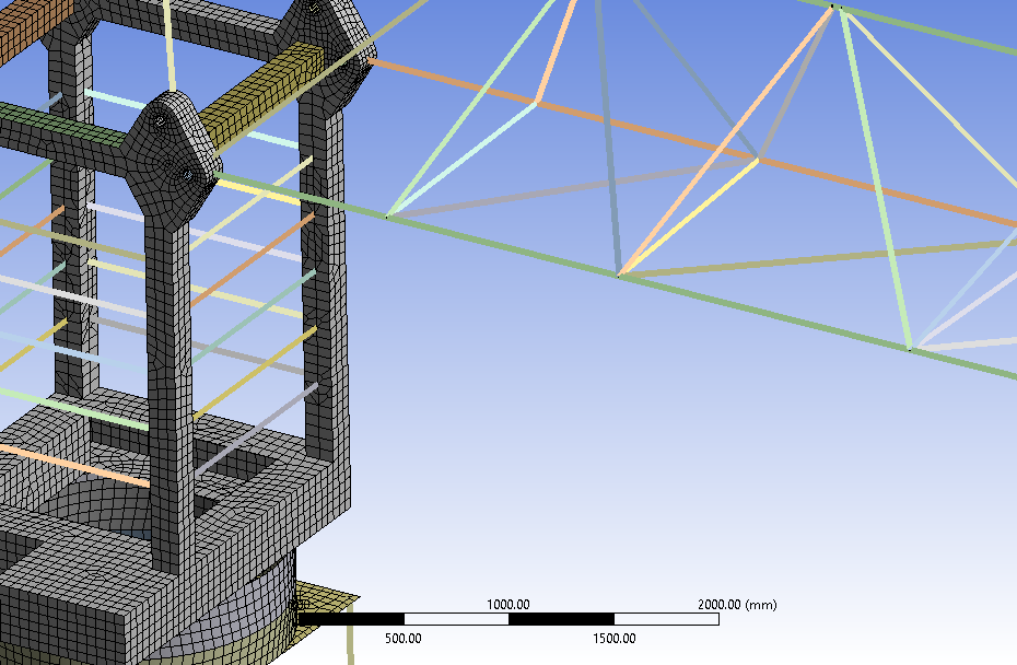
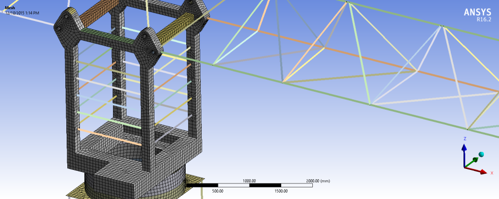
Although the total number of nodes would have been drastically reduced by converting solids into beams, the physical size of the structure itself still ensures the model is no small feat to mesh.
ANSYS Mechanical implements a number of time-saving features to make the meshing process as quick as possible, while still producing high quality meshes.
The first of these features is the ability to generate a finite element mesh in parallel, that is, all CPU cores may be used to mesh an assembly. This capability, shown to provide up to 27x speedup compared to a serial meshing process, is available to all users, regardless of whether the user owns an ANSYS HPC license.
With the release of ANSYS 16 earlier this year we also see the addition of the new Mesh Connection and Node Merge features, allowing the user to directly manipulate the finite element mesh at the node level. This functionality, combined with a wide range of intuitive local and global meshing controls, ensures the user has a tight control over mesh behaviour while not spending too much time in the meshing step of the analysis process.
Model Setup and Solution for Coupled Simulations
Despite all of the geometry cleanup and beam simplification operations performed, the fact remains that FE models in this industry are still extremely large models to solve. This is no problem for ANSYS Mechanical, which uses highly scalable, state-of-the-art solvers which can also harness the raw computing power of GPU computing cards.
Watch the video below to see how ANSYS takes advantage of modern processing power to allow for quick and easy model preparation.
Although an extremely powerful software package, this by no means translates to being difficult to use. Complex physics interactions such as fluid-structure interaction (FSI) studies to investigate wind loading on cranes are extremely simple to set up. Furthermore, the straightforward GUI remains the same regardless of whether the user is conducting a static, dynamic, modal or explicit analyses (amongst many others!).
In conclusion, the cranes and lifting industry presents a number of unique challenges when setting up and solving a finite element analysis. Beam extraction and extension has the potential to be a tedious process if Spaceclaim Direct Modeler were to be excluded from the workflow. Once geometry simplification has been completed, the sizeable geometry can be meshed with ease using the parallel meshing capabilities within ANSYS Mechanical. Connections between adjacent parts can be made on the node level, wherever the user sees applicable. Rapid solution times are made possible due to the highly scalable solvers used by ANSYS Mechanical, translating to faster results and a significantly shorter product development and testing schedule.

Can you please show us how to construct a huge tower crane in spaceclaim from top to bottom.. It’s a humble request.. Cz i really need to construct a huge towercrane in spaceclaim or design modler..
Hello,
first of all thank you very much for this post, very usefull !
Secondly, I still have a problem with extracting CAD parameters from spaceClaim, after open and extract beams of my CAD model. I can see a parameters tab in space claim but not the parameters tab in my ansys project window, if you have any informations…
Again thank you
Victor
Hello, I am a student in the College of Engineering. I want the scientific article on modeling and analysis of a tower crane using the ANSES program. Thank you
Hi Ahmed, if you’re looking for a published scientific article then we suggest you conduct a literature review using relevant keywords. If you’d simply like a tutorial or documented workflow for FEA of a tower crane using Ansys, then your local Ansys channel partner can assist you. If you’re in Australia or New Zealand, LEAP can assist – contact us via https://www.leapaust.com.au/contact/