Modern systems rely on the ability to ingest large amounts of data, process this data accurately, and act accordingly in a timely manner. The challenges faced in designing robust systems, particularly in the surveillance and detection space, make this an exceptionally complex design problem. Constantly evolving design requirements and the many moving parts that comprise these challenges require the system to perform across a host of use cases and operational conditions. But how does an engineer or system designer ensure their solution is fit for purpose, particularly when their metrics for mission success might change at a moment’s notice?
Digital Mission Engineering (DME) and the development of a suite of Design Reference Missions (DRMs) can allow a systems engineer to develop an interconnected system with the confidence it will perform across all intended and stressful operating conditions. To learn more about Digital Mission Engineering and how it is transforming traditional engineering processes see this post here.

Figure 1: Patrol boat with multi-function radar visualised
In this series we will explore how DME can be applied to the radar detection of an aircraft, which in turn will trigger the dynamic intercept of that aircraft. Throughout this mission, our system will be assessed on its ability to maintain crucial communication links between its multiple assets.

Figure 2: Unidentified Target Aircraft Passing over Patrol Boat
Contents:
Radar Detection
- Setup
- Detection Results
- Radar Jamming
Intercept Aircraft
- Aircraft Definition
- Flight Path Planning
Communication via LEO Constellation
- LEO Constellation
- Chain Access
- Communication Results
Radar Detection
Setup
Our DRM starts with an “unknown” aircraft passing over an offshore patrol boat north of Australia. As with all entries in this DME series, all data is notional and purely for educational purposes. The aircraft is detected by an onboard multifunction radar mounted on the boat. In its current configuration, the radar is comprised of three beams, a forward-facing fixed beam, a spinning search beam and a tracking beam that will lock onto the aircraft once line of sight is available. Each beam is defined via a series of user inputs and takes into account various physical and environmental effects, including the computed system noise temperature for the radar receiver.

Figure 3: Summary information for definition of each radar beam

Figure 4: Various factors included in the system noise temperature computation within STK
On the aircraft side of things, the flight path is defined using a series of basic point to point manoeuvres and STK’s default “fighter” aircraft profile. This profile includes information such as default cruising altitudes, fuel flow rates and basic aerodynamic performance information. Additionally, STK allows us to define a radar cross section (RCS) for the aircraft, which will form the basis of our detection process. Initially, the aircraft has been assigned a uniform RCS profile, while we validate the behaviour of our system. In turn, this will be replaced with a realistic RCS profile. As with all objects within STK, each element of the aircraft definition is setup such that they can be easily altered without having to rebuild the entire simulation. In turn, this facilitates rapid evaluation of a whole suite of potential use cases, including different aircraft models, RCS profiles and flight paths.


Figure 5: LHS uniform RCS profile used to validate system and RHS realistic RCS profile applied to aircraft afterwards
Detection Results
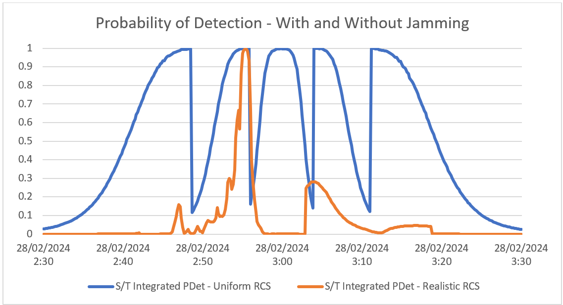
In this DRM, we’ve decided to use the Radar’s integrated Probability of Detection (PDet) as the primary measure of success for our system. This serves as an intuitive measure to describe the ability of our radar to detect various aircraft. Figure 8 shows the results of comparing the initial uniform RCS profile with the realistic HFSS RCS profile. As expected, the uniform profile provides a very predictable and symmetric response as the aircraft first nears, passes, and then travels away from the patrol boat. In its current configuration, the targeted radar beam is set up with four range based rectangular waveforms. As the radar swaps from one waveform to the next, we observe a sharp dip in detection. This occurs twice as the aircraft nears the patrol boat, and twice more as the aircraft travels further away.

Figure 6: Probability of Detection for uniform and realistic RCS Profiles
By comparison, the realistic RCS profile shows a much shorter period of confident detection and presents a much more sporadic detection result. From here, we now have a DRM which facilitates the assessment of system performance against specific design requirements. Moving forward, STK could now be paired with both inbuilt and external optimisation tools to allow for a parametric sweep of potential design points. This sweep might evaluate a number of radar specifications, aircraft altitudes or bank angles. Combined, this represents an incredibly efficient tool to evaluate and optimise these interconnected systems.
Radar Jamming
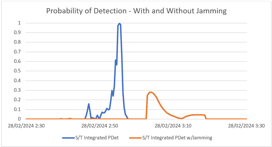
Building on this DRM, suppose the aircraft was equipped with a jamming device, tasked with disrupting the ship’s radar. The user can add a tracking jammer to the nose of the target aircraft, and immediately compare results across the two use cases. The following plot shows the new PDet with jamming alongside the initial results with no jamming.

Figure 7: Probability of detection without Jamming (Blue) and with Jamming (Orange)
This time the detection with jamming, shown here in orange, never exceeds 30%. Additionally, it only occurs after the aircraft has passed over the ship. Once again, this opens avenues to evaluate the system for the particular mission and provides an intuitive understanding as to the effectiveness of our proposed solution.
Next Time
Now that the foundation of this DRM is established, a dynamic response to the unknown target aircraft can be planned. Join us in part 2 of this series to explore how an intercept aircraft can be defined within STK, allowing for realistic modelling of real-world craft and dynamic flight planning capable of adapting to the target aircraft.

